
Search DesignFiX Knowledge Base by Keyword
Anchor tension and shear loads
The loads acting on an anchor plate or a fixture (tension and compression forces, shear loads, bending and torsion moments) shall distributed to tension and shear forces acting on the individual anchors of a group. Friction forces between anchor plate and concrete surface due to compression forces or bending moments are not considered in the verification for shear loads. The determination of the tension forces acting on an individual anchor of an anchor group is carried out in DesignFiX in accordance with ETAG 001, Annex C and TR 029 based on the theory of elasticity. A linear distribution of strains across the anchor plate or fixture and a linear relationship between strains and stresses is assumed (Figure 1).
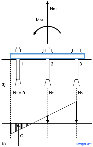
Distribution of the tension forces in the anchors and the strains below a steel plate resisting a tension load and a bending moment
Design of Fastenings for Use in Concrete – the CEN/TS 1992-4 Provisions.
Ernst & Sohn, Berlin 2013
This requires a rigid anchor plate or fixture that does not deform significantly. The plate or fixture should remain elastic under the design actions and its deformation should be compatible with the fastener’s displacement. In addition, further assumptions are valid according to ETAG 001, Annex C and TR 029:
- The stiffness of all anchors is equal and corresponds to the modulus of elasticity of the steel. The modulus of elasticity of the concrete may be taken from EN 1992-1-1:2004 (EN 1992-1-1:2004: Eurocode 2, Design of Concrete Structures – Part 1-1: General Rules and Rules for Building). In DesignFiX, as a simplification, the modulus of elasticity of concrete is assumed as Ec = 30 000 N/mm² independent of the concrete strength.
- Anchors in the area of compression below the base plate do not take tension Forces.
In certain rare situations there is a possibility that the iteration is inconclusive. This can e.g. happen when high compressive forces act upon the base plate. This leads to high actions and small anchor forces. This can also be the case when the anchors are positioned extremely unsymmetrically in two directions on the base plate or when the neutral axis is in close proximity of one anchor. In this situation the force in the anchor alternates from tension load to no tension load. After a predetermined number of iteration steps DesignFiX automatically stops the iteration, followed by a corresponding error message.
| External diameter d 1) or dnom 2) | 6 | 8 | 10 | 12 | 14 | 16 | 18 | 20 | 22 | 24 | 27 | 30 |
| Diameter df of the hole in the plate [mm] | 7 | 9 | 12 | 14 | 16 | 18 | 20 | 22 | 24 | 26 | 30 | 33 |
1) Bolt bears against the base plate or fixture
2) Sleeve bears against the base plate or fixture
These values are printed in the results.
- The relevant ETA contains the note: The design method according to ETAG 001, Annex C, Section 4.2.2 also applies to the hole diameters df specified in the annexes.
In this case, the distribution of the shear loads and torsional moments on the individual anchors of a group and the design are performed in DesignFiX according to ETAG 001, Annex C without restrictions. - The relevant ETA contains the note: The conditions in ETAG 001, Annex C, clauses 4.2.2.1a) and 4.2.2.2b) are not met, as the hole diameters in the fixture are greater than the values in Annex C, Table 4.1. Therefore, for fastenings with more than one anchor, the characteristic resistance of the group for steel failure VgRk,s should be limited to
2 · VRk,s of a single anchor.
If a group (nanchor > 2) and shear loads or torsional moments and annular gaps are present, then DesignFiX reduces the characteristic resistance of an anchor to:
VRk,s,red = 2 · VRk,s / nanchor
This ensures that the resistance of the entire group does not exceed the value 2 · VRk,s (VRk,s = characteristic resistance of a single anchor for steel failure under shear load according to the relevant ETA). - The relevant approval does not contain any information about the hole Diameters.
In this case, according to ETAG 001, Annex C, section 4.2.2.1, the design method does not apply because the hole diameters are too large. If a group (nanchor > 1) and shear loads or torsional moments act and annular gaps are present, DesignFiX responds with an error message stating that the annular gaps have to be filled or have to be eliminated by other suitable means.
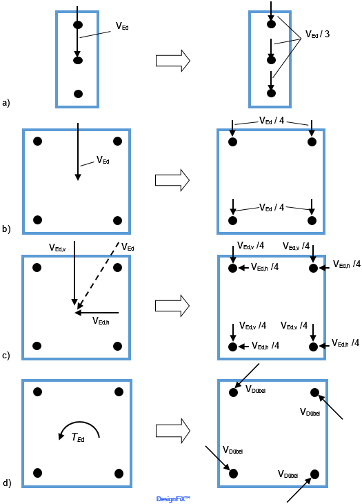
Distribution of a shear load on the individual anchors of a group for the failure modes steel failure and pry-out failure
- Group of three anchors, loaded by a shear load
- Group up of four anchors, loaded by a shear load
- Group of four anchors, loaded by an inclined shear load
- Group of four anchors, loaded by a torsion moment
Design of Fastenings for Use in Concrete – the CEN/TS 1992-4 Provisions.
Ernst & Sohn, Berlin 2013
Distribution of a shear load acting perpendicular to the edge on the individual anchors of a group for concrete edge failure
Design of Fastenings for Use in Concrete – the CEN/TS 1992-4 Provisions.
Ernst & Sohn, Berlin 2013
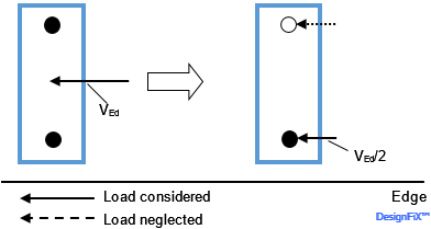
Unfavourable position of the anchors in the holes of a double fastening resisting a shear load perpendicular to the edge
Design of Fastenings for Use in Concrete – the CEN/TS 1992-4 Provisions.
Ernst & Sohn, Berlin 2013
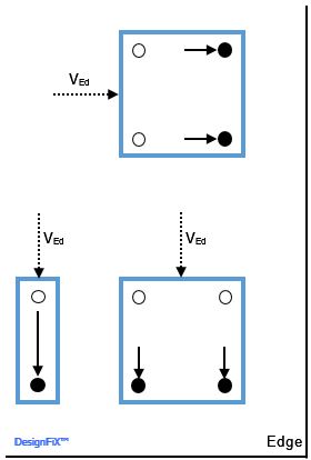
Fixings close to an edge and loaded by a shear load parallel to the edge may also fail due to concrete edge failure. In this case the anchor displacement under ultimate load is larger than with shear loads perpendicular to the edge. Thus, despite of the hole clearance between anchor and attachment all anchors of the group take up shear loads (Figure 5).
Distribution of a shear load acting parallel to the edge on the individual anchors of a group for concrete edge failure
Design of Fastenings for Use in Concrete – the CEN/TS 1992-4 Provisions.
Ernst & Sohn, Berlin 2013
Due to the above reasons the edge-parallel component of an inclined shear load is – due to reasons of equilibrium – distributed to all anchors of the group, while the component acting vertically to the edge is taken up only by the fasteners close to the edge (Figure 6).
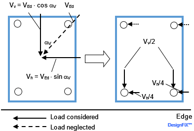
Distribution of an inclined shear load on the individual anchors of a group for concrete edge failure
Design of Fastenings for Use in Concrete – the CEN/TS 1992-4 Provisions.
Ernst & Sohn, Berlin 2013
Anchor shear forces directed away from the edge (e.g. due to a torsion moment) do not influence the concrete edge resistance and therefore may be neglected (Mallée, R.: Dübelgruppen am Bauteilrand unter Torsionsbeanspruchung. Beton- und Stahlbetonbau 97 (2002), Heft 2, S. 69-77 [in German]). Figure 7 shows this for a group of four anchors close to an edge loaded by a torsion moment. The edge-parallel shear forces on the two anchors remote from the edge and the shear force on the right anchor directed away from the edge may be neglected in the verification of concrete edge failure.
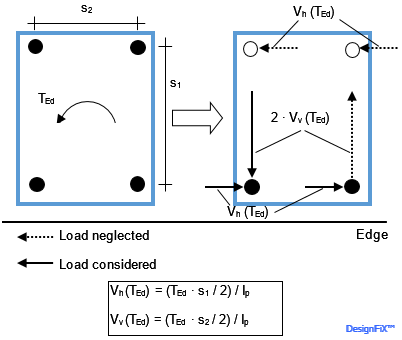
Distribution of a torsion moment on the individual anchors of a group for concrete edge failure
Design of Fastenings for Use in Concrete – the CEN/TS 1992-4 Provisions.
Ernst & Sohn, Berlin 2013
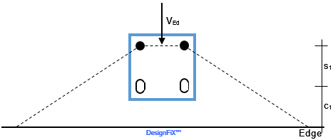
The assumption that for the verification of concrete edge failure only the unfavourable anchors close to the edge take up shear loads (Figure 3) may often lead to conservative results. More favourable results may be expected when the annular gap between anchor and base plate is filled with mortar of sufficient strength that guarantees that all anchors of the group take up shear loads. In this case two verifications are required (compare Figure 8). Figure 8 shows a quadruple fastening loaded by a shear force towards the edge.
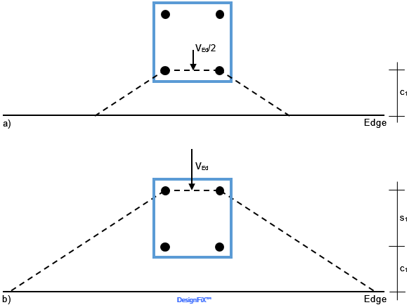
Double proof for concrete edge failure when the annular gap between anchor and base plate is filled with mortar of sufficient strength and the shear load acts perpendicular to the edge
- Verification of the anchors close to the Edge
- Verification of the anchors remote from the edge
The verification for the two anchors close to the edge is done for an edge distance of c1 and half the shear load (Figure 8a), while the proof of the two anchors remote from the edge is carried out for an edge distance of c = c1 + s1 and the entire shear load (Figure 8b). Much more complicated is the double proof in cases where an additional edge-parallel shear load is acting (Figure 9a). In this case the verification for the anchors close to the edge is done for VEd,v / 2 and VEd,h / 2 (Figure 9b). For the proof of the anchors remote from the edge it is essential to consider that the shear load parallel to the edge generates a torsion moment TEd = VEd,h ∙ s1 / 2 in the failure plane (Figure 9c).
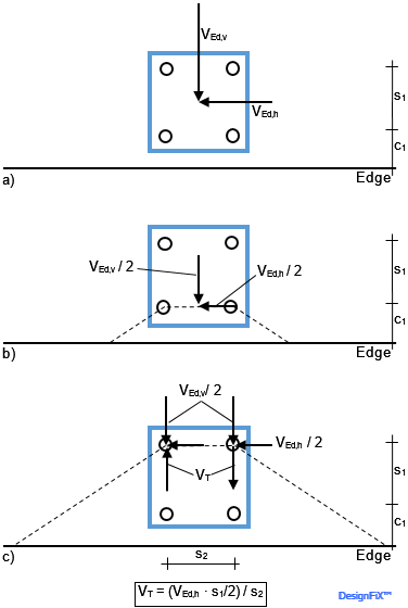
Double proof for concrete edge failure when the annular gap between anchor and base plate is filled with mortar of sufficient strength and the shear load acts inclined to the edge
- Shear loads
- Verification of the anchors close to the Edge
- Verification of the anchors remote from the edge
DesignFiX considers filled annular gaps between anchor and base plate only in order to permit groups of three, six and eight anchors close to an edge for the verification of concrete edge failure but despite of the filled annular gaps only the unfavourable anchor(s) close to the edge are considered. Additionally, DesignFiX follows the conservative approach that only these anchors take up the full shear load perpendicular to the edge. The distribution of the shear loads on the different anchor rows (close to and remote from the edge) and the mentioned double proof is not carried out in DesignFiX, because this approach contradicts ETAG 001, Annex C and TR 029. In addition, the consideration of the torsion moment due to edge-parallel shear loads leads often not to more economic solutions.
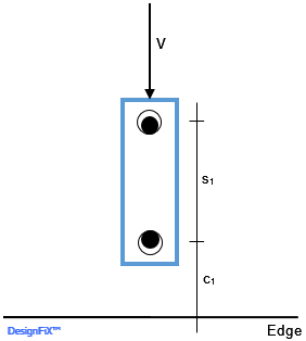
With fastenings close to an edge under shear load it can be advantageous to position the front anchors in slotted holes (Figure 10). This increases the effective edge distance for the verification of concrete edge failure to c = c1 + s1 and the characteristic resistance increases accordingly.
Example of a shear loaded anchor group with slotted holes
DesignFiX permits in the actual version no shear loads perpendicular to slotted holes. Therefore no additional torsion moment due to an edge-parallel shear load has to be considered.