Search DesignFiX Knowledge Base by Keyword
Tab – BASE MATERIAL
The tab BASE MATERIAL in the module Anchor Design contains five groups:
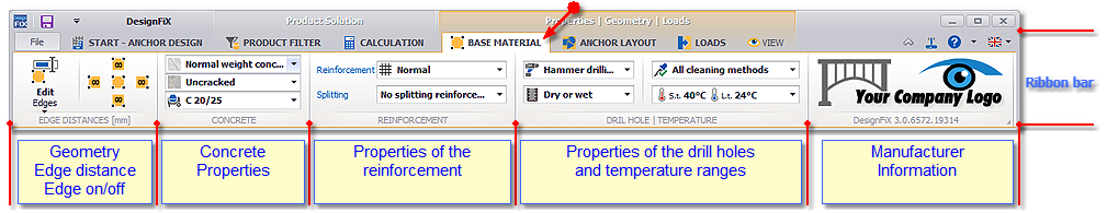
EDGE DISTANCES
Edit geometry
This function opens the tabular input window in the program area 3D-Modell.
The section concrete is opened in the input window and all other sections are closed. With the lower part of the button you can alternatively open all sections of the window or close it. The input window offers an extremely practical and convenient alternative to entering the dimensions and loads.
The following values can be entered:
| cx , cy | Distances between anchors and edges in positive/negative X- and Y-direction. With the function ∞ (infinity) an edge can be removed or negated. |
| h | Thickness of the component |
Alternatively, these values can be entered directly in the corresponding input field of the 3D-drawing. A direct link exists between the input fields of the 3D-drawing and the input window. If the cursor is positioned in an input field of the 3D-drawing then the corresponding field in the input window is marked (hover effect) and vice versa. This makes it easier to navigate.

Component edges
With these functions, the individual component edges are added or removed. With the central function all edges can be negated simultaneously. The same features are also available in the input window in the 3D-Model.

Edge distances affect the characteristic resistance for conical concrete break-out and splitting of the component under tension loads and for pry-out failure and concrete edge failure under shear loads.
CONCRETE
With this function, the state of the base material (cracked / non-cracked concrete) and the actual concrete strength class can be selected. Both parameters influence the characteristic resistance for pull-out/pull-through failure (mechanical anchors), combined pull-out and concrete failure (chemical anchors), conical concrete break-out and splitting of the component under tension loads and for pry-out failure and concrete edge failure under shear loads.
In accordance with ETAG 001, Annex C and TR 029, Section 4.1, non-cracked concrete may be assumed only if it is proved in each case that under service conditions the anchor with its entire embedment depth is positioned in non-cracked concrete.
For anchorages subjected to a resultant load FSk ≤ 60 kN, non-cracked concrete may be assumed if the following equation is observed:![]()
With:![]() stresses in the concrete due to external loads, including anchor loads
stresses in the concrete due to external loads, including anchor loads![]() stresses in the concrete due to restraint of intrinsic imposed deformations (e.g. shrinkage of concrete) or extrinsic imposed deformations (e.g. due to displacement of support or temperature variations).
stresses in the concrete due to restraint of intrinsic imposed deformations (e.g. shrinkage of concrete) or extrinsic imposed deformations (e.g. due to displacement of support or temperature variations).
If no detailed analysis is conducted, then = 3 N/mm² should be assumed. This value is also used in Eurocode 2 (EN 1992-1-1:2004: Eurocode 2, Design of Concrete Structures – Part 1-1: General Rules and Rules for Buildings) for the determination of the minimum reinforcement in reinforced concrete components for the limitation of the crack width in the serviceability limit state.
The stresses ![]() and
and ![]() are calculated assuming that the concrete in non-cracked (state I). For plane concrete members which transmit loads in two directions (e.g. slabs or walls) the equation given above shall be fulfilled for both directions.
are calculated assuming that the concrete in non-cracked (state I). For plane concrete members which transmit loads in two directions (e.g. slabs or walls) the equation given above shall be fulfilled for both directions.
REINFORCEMENT
The characteristic resistance for conical concrete break-out and for splitting of the component under tension loads as well as for pry-out failure under shear loads can be affected negatively by a dense surface reinforcement if the anchors are positioned in the concrete cover or close to this reinforcement. This has three reasons: Bond stresses associated with the reinforcement are superimposed on the tensile stresses generated by the anchors. Closely spaced reinforcement bars disrupt the transfer of tension forces from the anchor into the concrete member (so-called “perforated concrete cover”). Additionally the anchors may be located in areas where the concrete strength is of poorer quality than in the middle of the concrete member. No negative effect is expected if the axial spacing of the reinforcement bars is independent of the bar diameter ≥ 150 mm or if for reinforcement bars with a diameter of maximum 10 mm the axial spacing is ≥ 100 mm. This can be selected in the function Reinforcement.
Verification for splitting is not required if the edge distance in all directions is c ≥ 1,2 ∙ ccr,sp and the thickness of the concrete component is h ≥ 2 ∙ hef (mechanical post-installed anchors) or h ≥ 2 ∙ hmin (chemical post-installed anchors) or if the selected anchor is suitable for use in cracks, the verification is carried out for cracked concrete and a reinforcement is present that limits the crack width to wk ≈ 0,3 mm, taking into account the splitting forces generated by the anchors. The presence of such a reinforcement can be confirmed in the function “Splitting“.
DRILL HOLE | TEMPERATURE
The characteristic resistance of chemical anchors for combined pull-out and concrete failure can be affected by the drilling method (hammer/diamond drilling), the condition of the concrete (dry and wet, flooded holes), the intensity of the hole cleaning or the temperature of the base material in the area of the anchor. All mentioned parameters influence the characteristic bond resistance τRk of the mortar which is given in the corresponding European approval. They can be selected in this section.
In the temperature range a distinction is made between maximum short-term and maximum long-term temperatures. Click on the temperature to open a list (ComboBox) with all available temperature ranges and select the desired temperatures. Chemical anchors that do not meet the temperature requirements will automatically disappear in the product tree. If the selected temperature range lies between the ranges specified in the approval of an anchor, then the bond stress for the higher temperature is used. This approach is conservative. E. g., if an approval contains characteristic bond strengths for temperature ranges 60°/35° and 72°/43° and you have selected the range 60°/43°, then the bond strength for the higher temperatures (72°/43°) is used for combined pull-out and concrete failure.
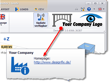
DesignFiX Information
If you select a product on the left side of the user interface then the logo of the manufacturer will be displayed at the right edge of the ribbon bar that contains further information. If DesignFiX finds a LiveUpdate then this information will appear at this point by means of an additional link.