Search DesignFiX Knowledge Base by Keyword
Curious #1: Contradictory results / hef

The design of anchors in accordance with European Regulations (ETAG 001, Annex C and Technical Report TR 029) leads in the overwhelming number of applications to logical results. In certain cases, also strange design results can occur that contradict the expectations of the user and naturally lead to doubts about the accuracy of the used design program (Mallée, R.: Anmerkungen zur Bemessung von Dübeln nach europäischen Regelungen (Comments on the design of anchors according to European regulations). Verlag Ernst & Sohn, Beton- und Stahlbetonbau, 2014, No. 10, pp. 699 – 712, in German). For example, the characteristic resistance of a fastening with tensioned injection anchors may decrease for the failure mode ‘Splitting’ with increasing embedment depth of the anchors. This behaviour seems to be illogical.
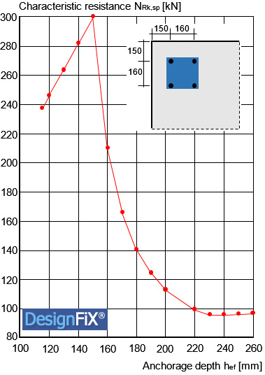
The figure shows the characteristic resistance of a group consisting of four injection anchors M16 in a corner of a component for the failure mode ‘Splitting’ as a function of the anchorage depth. The dimensions are: Axial spacing s = 160 mm, edge distances c = 150 mm and component thickness h = 300mm. The concrete is non-cracked and corresponds to class C20/25.
It can be seen that the characteristic resistance increases for small anchorage depths, drops significantly between hef = 150 mm and hef = 230 mm and slightly increases again for hef > 230 mm. This unexpected behavior is due to the approaches for the characteristic edge distance ccr,sp. In accordance with the European approval of the selected injection anchor this distance depends on the ratio of the component thickness h and the embedment depth hef:

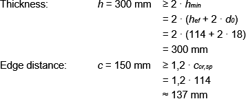
For embedment dephts hef ≤ 114 mm, the verification for splitting failure can be omitted because the conditions according to ETAG 001, TR 029 are adhered to with respect to the component thickness and the edge distance:

For embedment depths between hef = 115 mm and hef = 150 mm the resistance increases as expected. In this area, the characteristic edge distance ccr,sp increases proportionally to the anchorage depth hef (Equation (3)). In addition, no edge effect is present, since the edge distance is with c = 150 mm greater than the characteristic value. The negative effect of the two axial spacing s = 160 mm with increasing anchorage depth, is more than offset by the increase of the resistance N°Rk,c of a single anchor.
Between hef = 150 mm and hef = 230 mm the characteristic resistance is reduced considerably due to the disproportionate increase of the characteristic edge distance from ccr,sp = 150 mm to ccr,sp = 518 mm in accordance with Equation (2). This reduces the ratio of the idealized fracture surfaces from Ac,N/A°c,N = 2,351 to Ac,N/A°c,N = 0,639, and of the edge factor from ψs,N = 1,000 to ψs,N = 0,787. At the same time the factor for the influence of the component thickness decreases from ψh,sp = 1,375 to ψh,sp = 1,083. The described reduction of the different factors is not compensated by the increase of the resistance of a single anchor from N°Rk,c = 92,77 kN to N°Rk,c = 176,15 kN with increasing anchorage depth:
hef = 150 mm: N°Rk,c ∙ Ac,N/A°c,N ∙ ψs,N ∙ ψh,sp = 92,77 ∙ 2,351 ∙ 1,000 ∙ 1,375 = 299,9 kN
hef = 230 mm: N°Rk,c ∙ Ac,N/A°c,N ∙ ψs,N ∙ ψh,sp = 176,15 ∙ 0,639 ∙ 0,787 ∙ 1,083 = 95,9 kN
The amount of decrease of the characteristic resistance in the range between hef = 150 mm and hef = 230 mm depends largely on the number of component edges (see Table).

For embedment depths hef > 230 mm the characteristic resistance rises slightly again. In this area the characteristic edge distance ccr,sp increases – as for embedment depths hef ≤ 150 mm – no longer disproportionately, but linearly with the anchorage depth.
It could be shown that the curious design results are not due to errors in the design, but the design process itself. Die Special Activity Group SAG 4 ‘Fastenings to Structural Concrete and Masonry Structures’ of the International Federation for Structural Concrete (fib) has formed a working group that deals with the failure mode ‘Splitting’. The author is member of this activity group. The conclusions of this group remain to be seen.

