
Search DesignFiX Knowledge Base by Keyword
Curious #3: Steps in the characteristic resistance

When groups of mechanical or chemical anchors close to a component edge fail due to ‘Concrete cone failure’ then steps may occur in the characteristic resistance as soon as the axial spacing perpendicular to the edge exceeds the characteristic value scr,N.
The characteristic resistance of chemical anchors for the failure modes ‘Splitting’ and ‘Combined pull-out and concrete failure’ may decrease despite increasing embedment depths. This behaviour that contradicts the expectations of engineers was described in Part 1 and 2 of this posts and the reasons for the illogical results were discussed.
Similar curious results occur with anchor groups close to an edge and the failure modes ‘Concrete cone failure’ (mechanical and chemical anchors) and ‘Splitting’ (mechanical anchors) when the axial spacing of the anchors perpendicular to the edge exceeds the characteristic value scr,N (Mallée, R.: Anmerkungen zur Bemessung von Dübeln nach europäischen Regelungen (Comments on the design of anchors according to European regulations). Ernst + Sohn, Berlin, Beton- und Stahlbetonbau, 2014, pp. 699-712 (in German)). This has the following reason:
The concrete break-out cone of an anchor under tensile load begins at the level of the expansion or undercut area and extends at an angle of approximately 35° to the concrete component surface. On this assumption, the cone diameter on the concrete surface is approximately three times the anchor depth (Figure 1a). This value is referred to as the characteristic axial spacing scr,N. In design, the break-out cone is idealized by a pyramid with the edge length scr,N. The area of this idealized break-out body on the concrete surface corresponds to a square with the edge length scr,N = 3 ∙ hef. It is referred to as A°c,N and is A°c,N = (3 ∙ hef)² (Figure 1b).
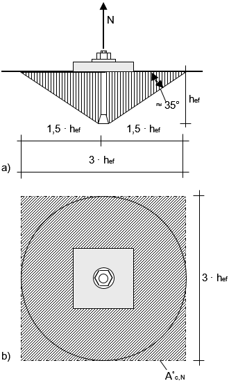
Figure 1:
Concrete cone failure body of a single anchor without edge influence (after: Fuchs, W.; Eligehausen, R.; Breen, J. E.: Concrete Capacity Design (CCD). Approach for Fastening to Concrete. ACI Structural Journal, Vol. 92 (1995), No. 1. pp. 73-94)
If the area A°c,N is available to an anchor on the concrete component surface, the anchor gains its maximum load bearing capacity. If this is not the case, the resistance of the anchor is reduced in the ratio Ac,N / A°c,N where Ac,N is the area of the idealized failure body of the fastening. An example for the determination of this area is shown in Fig. 2a.
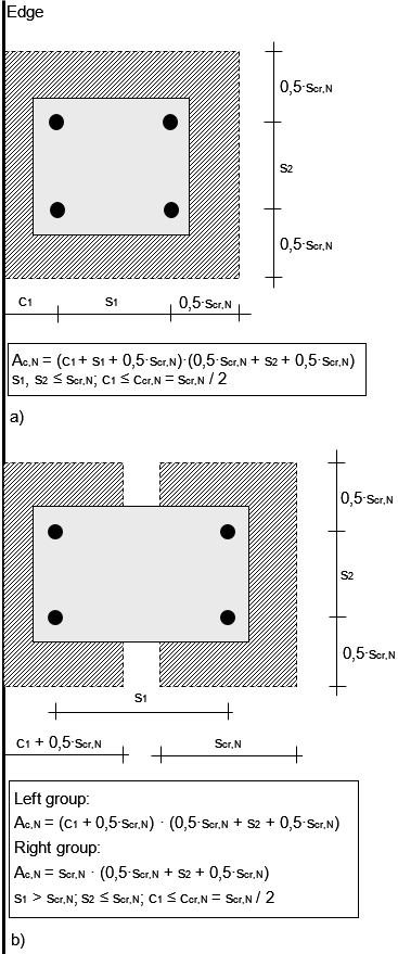
Figure 2:
Projected area of the idealized failure body of a group of four anchors close to an edge for concrete cone failure (Mallée, R.: Anmerkungen zur Bemessung von Dübeln nach europäischen Regelungen (Comments on the design of anchors according to European regulations). Ernst + Sohn, Berlin, Beton- und Stahlbetonbau, 2014, pp. 699-712 (in German))
a) Axial spacing s1, s2 ≤ scr,N
b) Axial spacing s1 > scr,N, s2 ≤ scr,N
If the spacing s1 in Figure 2a exceeds the characteristic value scr,N, the break-out bodies of the left and right anchors do not overlap, the anchors do not interfere with each other and therefore no longer belong to the same group. The fastening therefore consists of two double fastenings, one close to the edge and the other remote from the edge (Figure 2b), both of which are separately verified.
The transition from the quadruple group (Figure 2a) to two independent groups (Figure 2b) leads to a step in the characteristic resistance of groups close to an edge. Figure 3 shows the degree of utilization ßN,c = NgEd / NRd,c of a group with four chemical anchors M12 at the component edge for ‘Concrete cone failure’, where NgEd is the design value of the sum of all tensile loads acting on the anchors of the group, and NRd,c = NRk,c / γMc is the design value of the resistance of the group. The embedment depth of the anchors is hef = 100 mm and the concrete of strength class C20/25 is non-cracked. The characteristic distances for concrete cone failure are scr,N = 3 ∙ hef = 300 mm and ccr,N = 1.5 ∙ hef = 150 mm. The edge distance and the edge-parallel axial spacing are constant with c1 = 60 mm and s2 = 200 mm, respectively, while the axial spacing perpendicular to the edge is varied between s1 = 60 mm and s1 = 400 mm. The tensile load acting concentrically at the center of gravity of the four anchors is NEd = 30 kN.
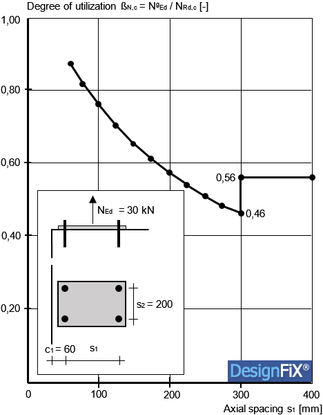
Figure 3:
Degree of utilization of a quadruple fastening with chemical anchors M12 close to an edge as a function of the axial spacing s1 (Mallée, R.: Anmerkungen zur Bemessung von Dübeln nach europäischen Regelungen (Comments on the design of anchors according to European regulations). Ernst + Sohn, Berlin, Beton- und Stahlbetonbau, 2014, pp. 699-712 (in German))
As expected, the degree of utilization continuously decreases up to a spacing s1 = scr,N = 300 mm, because the break-out bodies of the left and right anchors are less and less overlapping. The minimum ßN,c = NgEd / NRd,c = 0,46 is achieved with a spacing s1 = 300 mm. At this axial spacing, the break-out bodies of the left and right anchors do not overlap, but they touch each other and are therefore considered to be a group. If the spacing s1 is only slightly increased, the degree of utilization increases abruptly by more than 20% to NgEd / NRd,c = 0,56. This increase can be explained as follows.
As long as the four anchors of the fastening belong to one group, they fail jointly and form a common break-out body (Figure 2a). When calculating the area Ac,N of the idealized break-out body, the edge influence is “smeared” on all four anchors, that is, the two anchors remote from the edge positively influence the behavior of the two anchors close to the edge. If, however, two independent groups are present (Figure 2b), then both groups must be verified separately. If the tensile load acts centrically, as in the present example, the double fastening close to the edge is decisive and the component edge only affects the load-bearing capacity of this group. As a result, the positive influence of the two anchors remote from the edge is eliminated and the degree of utilization of the relevant group increases.
The described step in the degree of utilization can theoretically be avoided if the fastening is considered as one group even at large axial spacing, and when the axial spacing used to calculate the area Ac,N is limited to the value scr,N. In this case, the area of the idealized break-out body according to Figure 2b results from the sum of the areas of the two anchors close and remote to the edge:
Ac,N = (c1 + 0,5 ∙ scr,N + scr,N) ∙ (0,5 ∙ scr,N + s2 + 0,5 ∙ scr,N)
In doing so, however, it is assumed that the anchors of the group always fail together even with a large spacing s1 and form a joint break-out body. One can assume that this is true as long as the spacing s1 is not greater than about 3 to 4 times the embedment depth. If the spacing is larger, the two anchors close to the edge will fail first. Subsequently, no additional load is possible, because the two anchors remote from the edge cannot take up the moment occurring after breaking of the front anchors and also fail. A “smearing” of the edge distance on all anchors of the fastening is therefore not realistic with large spacing s1.
One possible solution would be to modify the current design method so that the resistance of each individual anchor in the group is calculated and compared with the load acting on this anchor. The anchor with the highest degree of utilization would then be decisive for the failure of the whole group. However, a corresponding approach for the consideration of load eccentricity has so far been lacking. The eccentricity factor ψec,N used in the current design method is valid for the group and not for the individual anchors of a group (Riemann, H .: Das “erweiterte κ-Verfahren” für Befestigungsmittel, Bemessung an Beispielen von Kopfbolzenverankerungen. (The “expanded κ-method” for fastenings, design examples for headed anchors). Betonwerk + Fertigteil-Technik, Vol. 12, pp. 808-815).
Up to the proposed modification of the design method, the steps in the load capacity of anchor groups close to the edge cannot be avoided. Until then, however, it is to be hoped that this contribution will help with discussions between our customers and users of the design program DesignFiX.