
Search DesignFiX Knowledge Base by Keyword
Earthquake ETAG 001, TR 045
What about design with requirements on the ductility of the anchors in accordance with TR 045, Section 5.3b?

Technical Report TR 045 offers different design options:
- Capacity design in accordance with TR 045, Section 5.3a1
- Elastic design in accordance with TR 045, Section 5.3a2
- Design with requirements on the ductility of the anchors in accordance with TR 045, Section 5.3b
- With capacity design the anchors are designed for the maximum load to be resisted by the attachment. In this way the fastening is protected against overloading and brittle concrete failure is permissible.
- With elastic design the anchors are designed for the maximum load obtained from the design load combinations according to EN 1998-1:2004 that include seismic actions EE,d at ultimate limit state (ULS). Elastic behavior of both, the fastening as well as the structure is assumed. Uncertainties in the model to derive seismic actions on the fastening shall be taken into account.
- With design for ductile behavior of the anchors additional ductility requirements shall be met. Thus, steel failure of the anchors is ensured and brittle concrete failure can be excluded with high probability. Standard commercial anchors do not meet the ductility requirements. Therefore, the design option “Ductile steel failure” is not considered in DesignFiX.
Capacity design:
The anchors are designed for the maximum load that can be transmitted to the anchors by the attachment. Enter in the 3D-model the maximum tension- and/or shear loads that cause yielding of the attachment welded to the anchor plate (Fig. 41a) taking into account strain hardening and material over-strength or enter the maximum load that can be transferred to the fastening by the non-yielding attachment or the structure (Fig. 41b).
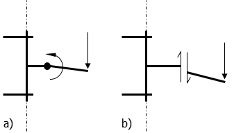
Figure 41:
Protection of the fastening under seismic Actions
- a) Yielding of the attachment
- b) Capacity of the attachment
Elastic design:
Enter in the 3D-model the maximum load obtained from the design load combinations that include seismic actions EE,d according to EN 1998-1:2004 at ultimate limit state (ULS) assuming an elastic behavior of the fastening and of the structure. Uncertainties in the model to derive seismic actions on the fastening shall be taken into account. For connections between structural elements (Type ‘A’) the action effects shall be derived according to EN 1998-1:2004 with a behavior factor q = 1.0. For attachments of non-structural elements the behavior factor is qa = 1.0. If action effects are derived in accordance with the simplified method given in TR 045, Section 5.5.4 with qa = 1.0 they shall be multiplied by an amplification factor of 1.5. If the action effects are derived from a more precise model this amplification factor may be omitted.
The design value of the effect of seismic actions EE,d shall be determined according to EN 1998-1:2004 and TR 045, Section 5.3. Additional requirements including vertical seismic actions acting on non-structural elements are provided in TR 045, Section 5.5. It shall be assumed that the maximum actions under tension and shear act simultaneously if no more accurate model is used.
More detailed information can be found in our DesignFiX user manual, section earthquake.