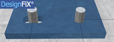
In some applications it can be advantageous to arrange individual anchors in a group in slotted holes.
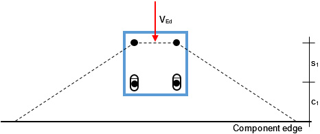
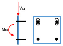
In some applications it can be advantageous to arrange individual anchors in a group in slotted holes. If, for example, a fastening is loaded by a shear force in the direction of the edge of the component, the characteristic resistance for concrete edge failure is significantly increased if the anchors near the edge are positioned in slotted holes (Figure 1a). However, elongated holes can also have a positive effect on the load-bearing behaviour in the case of fastenings remote from the edge, because this means that tensile and shear stressed anchors can be separated from one another. Figure 1b shows an example. In this case, the two upper anchors are loaded by pure tensile forces and the two lower anchors by pure shear forces. Only if the anchor plate protrudes a great deal will the lower anchors be subjected to additional low tensile forces.
Figure 1a demonstrates the advantages of slotted holes using the example of a group of four anchors close to an edge. The front anchors are located in slotted holes and the group is loaded by a shear load perpendicular to the edge. As a consequence of the slotted holes concrete edge failure occurs at the back anchors, the effective edge distance increases to c = c1 + s1 and the characteristic resistance increases accordingly.
Figure 1a:
Figure 1b:
In addition to shear loads in direction of the slotted holes simultaneously shear loads can act perpendicularly to the slotted holes (Fig. 2a). As shown in the following, this can lead to problems with fastenings close to the edge (Fig. 1a). For this reason, DesignFiX allows shear forces perpendicular to slotted holes only for fastenings remote from the edge (Fig. 1b).
Fastenings close to the edge in slotted holes and shear forces acting perpendicular to these holes are not mentioned in the design guidelines. Consequently, no information is given about how to perform the proof of concrete edge failure. This task can be solved in accordance with the principles of the distribution and the magnitude of the shear loads according to ETAG 001, Annex C and TR 029, Section 4.2.2. Of course, the conditions of equilibrium are to be met.
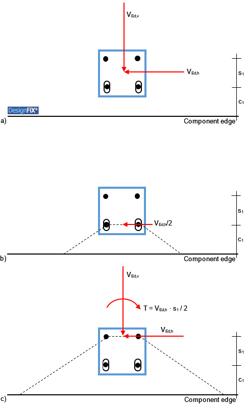
Figure 2a shows a group of four anchors close to an edge, which is loaded by a shear load inclined relative to the edge. The two front anchors are positioned in slotted holes.
Since the concrete edge failure can occur at the front and at the back anchors a double proof needs to be performed. In the first proof concrete edge failure of the front anchors is assumed (Figure 2b). As the shear load acting parallel to the edge is distributed by definition on all anchors of the group the value of the design action is VEd = VEd,h/2. Because of the slotted holes no shear load is acting perpendicular to the component edge.
Figure 2: Group of four anchors close to an edge, loaded by a shear load inclined relative to the edge
a) Geometry and load
b) Proof of concrete edge failure at the front anchors
c) Proof of concrete edge failure at the back anchors
In the second proof concrete edge failure of the back anchors is assumed (Figure 2c). Under this assumption the two front anchors are positioned in the failure body and therefore do not take up shear loads. This means that all the shear loads acting parallel and perpendicular to the component edge have to be taken up by just the two back anchors. However, the shear load VEd,h acts eccentrically relative to the centre of gravity of the two back anchors (e = s1/2). For reasons of equilibrium, the torsional moment T = VEd,h ∙ s1/2 resulting from this eccentricity has to be taken into account in the design. This will further increase in the example in Figure 2 the shear load acting on the right anchor, while the shear load on the left anchor decreases and with large torsional moment can even alter its direction.
The described distribution of the shear loads on the individual anchors of a group is good engineering practice. Surprisingly, however, that some design programs available on the market neglect the eccentricity of the edge parallel shear load relative to the centre of gravity of the two back anchors and thus do not fulfil the equilibrium conditions. The resulting error increases with increasing ratios s1/s2 and/or VEd,h/VEd,v. Furthermore, the programs also distribute the shear load acting parallel to the edge on all anchors of the group although the two front anchors are located in the concrete failure body and therefore cannot take up any shear loads. In the following example it is shown that this approach can lead to unsafe design results.
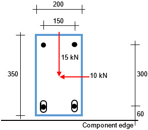
Figure 3 shows a group of four injection anchors M10 (steel strength class 5.8) close to an edge. The anchorage depth is hef = 60 mm. The concrete is cracked and normally reinforced and corresponds to the strength class C20/25. No edge reinforcement is available (no edge and hanger reinforcement). The component thickness h = 200 mm.
Figure 3:
Design approach No. 1:
Conditions for the proofs:
- Concrete edge failure occurs at the back anchors
- The front anchors are located in the failure body and thus do not take up any shear loads
- The eccentricity of the shear load acting parallel to the edge relative to the centre of gravity
of the two back anchors is taken into account - The conditions of equilibrium are fulfilled
Under these assumptions, the following shear loads act on the two back anchors:
- Left anchor:
Vv = -2,50 kN (directed away from the edge)
Vh = 5,00 kN
V = 5,59 kN
- Right anchor:
Vv = 17,50 kN (directed towards the edge)
Vh = 5,00 kN
V = 18,20 kN
Proofs:
- Steel failure:
VSd > VRk,s / γMs
18,20 > 15,00/1,25 = 12,00 → Use of capacity: 152 %
- Pry-out failure → Since the direction of the individual shear loads within the group alters the proof is performed for the most unfavourable anchor of the group (ETAG 001, Annex C and TR 029, Section 5.2.3.3):
VSd > VRk,cp / γMcp
18,20 > 24,19/1,50 = 16,13 → Use of capacity: 113 %
- Concrete edge failure:
VSd = (17,50² + 10,00²)0,5 = 20,16 kN
VSd < VRk,c / γMc
20,16 < 75,74/1,5 = 50,49 → Use of capacity: 40 %
Conclusion:
The load-bearing capacity of the group is insufficient. The values of the design resistances for the failure modes steel failure and pry-out failure are less than the values of the design actions. Only the resistance for concrete edge failure is sufficient. This shows the benefits of slotted holes.
If we neglect – as some design programs available on the market do – the eccentricity of the edge parallel shear load relative to the centre of gravity of the two back anchors and if we assume that the two front anchors take up shear loads even though they are located in the failure body, then we face a completely different situation (see design approach No. 2):
Design approach No. 2:
Conditions for the proofs:
- Concrete edge failure occurs at the back anchors
- Even though the two front anchors are located in the failure body they take up shear loads
- The eccentricity of the shear load acting parallel to the edge relative to the centre of gravity
of the two back anchors is not taken into account - The conditions of equilibrium are not fulfilled
Proofs:
- Steel failure:
VSd = (15,00² + 5,00²)0,5/2 = 7,91 kN
VSd < VRk,s / γMs
7,91 < 14,50/1,25 = 11,60 → Use of capacity: 68 %
- Pry-out:
VSd = (15,00² + 5,00²)0,5 = 15,81 kN
VSd < VRk,cp / γMcp
15,81 < 48,91/1,50 = 32,61 → Use of capacity: 48 %
- Concrete edge failure:
VSd = (15,00² + 5,00²)0,5 = 15,81 kN
VSd < VRk,c / γMc
15,81 < 56,41/1,5 = 37,61 → Use of capacity: 42 %
Conclusion:
Ignoring the eccentricity of the edge parallel shear load and thus disregarding the equilibrium can lead to unsafe design results. One gets the impression that the capacity of the fastening is sufficient, but this is definitely wrong if the eccentricity is taken into account correctly (see design approach No. 1).
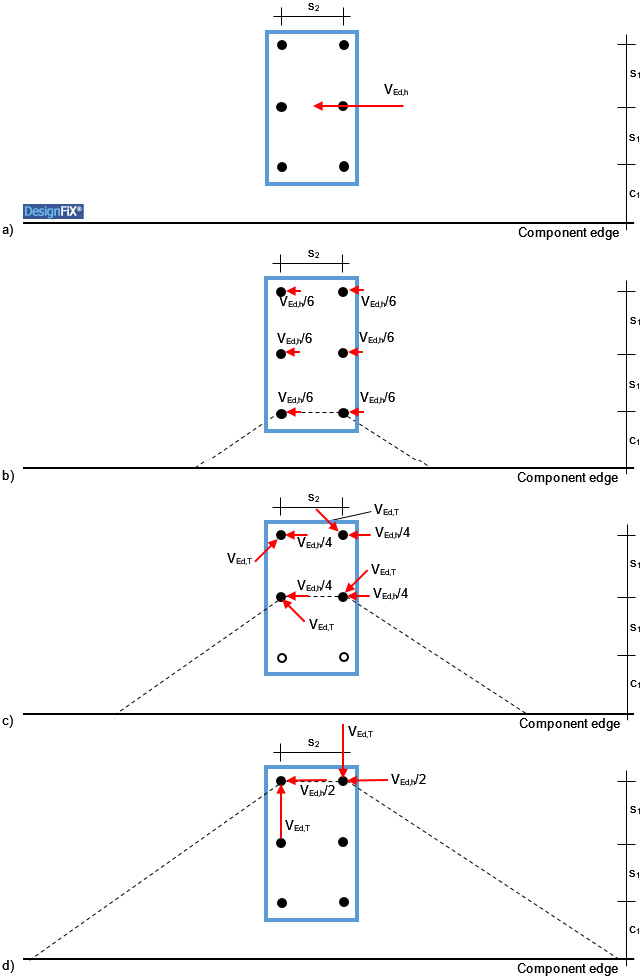
The International Federation for Structural Concrete (fib), an international association on matters of reinforced and prestressed concrete construction, has established a working group, which deals with fixing technology (Special Activity Group SAG 4: Fastenings to Structural Concrete and Masonry Structures). Its members include experts from many countries. The group is a recognized authority on all matters of the design of anchors. The results of many years of work of this group are summarized in a comprehensive report, which contains the current state-of-the-art (International Federation for Structural Concrete (fib): Design of Anchorage in Concrete. Bulletin 58, Lausanne 2011). As in ETAG 001, no shear loads perpendicular to slotted holes are discussed in Bulletin 58, however, a comparable situation is described: The distribution of an edge parallel shear load on the individual anchors of group of six anchors close to an edge, while the failure crack runs either through the front, middle or rear anchors (Figure 4).
If the failure crack runs through the front anchors (Figure 4b), then the shear load is VEd = 2 ∙ (VEd,h/6). The shear loads on the remaining four anchors need not be considered in the proof of concrete edge failure because they are located behind the failure crack (see ETAG 001, Annex C and TR 029, Figure 4.7).
If the failure crack runs through the middle anchors (Figure 4c), then the edge parallel shear load is equally distributed among the remaining four anchors. In addition, the torsional moment VEd,T is taken into account, resulting from the eccentricity of the shear load VEd,h relative to the centre of gravity of the four anchors. The proof for concrete edge failure is performed for the edge parallel shear load VEd = 2 ∙ (VEd,h/4) of the two anchors located in the failure crack plus the load components resulting from the torsional moment that are directed towards or parallel to the edge. Shear components that are directed away from the edge may be neglected in the proof for concrete edge failure (ETAG 001, Annex C, Figures 5.8 and 5.9 or ETAG 001, TR 029, Figures 5.9 and 5.10, respectively).
If the failure crack runs through the back anchors (Figure 4d), then the edge parallel shear load is equally distributed among the remaining two anchors. In addition, the torsional moment VEd,T is taken into account, resulting from the eccentricity of the shear load VEd,h relative to the centre of gravity of the two anchors. The proof for concrete edge failure is then performed for the edge parallel shear load of the anchors VEd = 2 ∙ (VEd,h/2) plus the load components resulting from the torsional moment that are directed towards the edge.
The load distribution in Figure 4 confirms the correctness of design approach No. 1.
Figure 4: Distribution of a shear load acting parallel to an edge on the individual anchors of a group of six (after: International Federation for Structural Concrete (fib): Design of Anchorages in Concrete. Bulletin 58, Lausanne, 2011)
a) Geometry and load
b) Concrete edge failure of the front anchors
c) Concrete edge failure of the middle anchors; VEd,T = (VEd,h ∙ s1/2) / (2 ∙ (s1² + s2²)0,5)
d) Concrete edge failure of the back anchors; VEd,T = VEd,h ∙ s1 / s2

