

If the number of tensioned anchors changes within an anchor group close to an edge due to variable loads, then there may be steps in the characteristic resistance for ‘Concrete cone failure’.
In Part 3 of this posts, it was shown that, in the case of anchor groups close to a component edge, steps occur in the characteristic resistance for the failure mode ‘Concrete cone failure’ when the axial spacing perpendicular to the edge exceeds the characteristic value scr,N. This behavior contradicts the expectations of the engineers and leads to discussions.
Similar contradictory results are to be expected if the axial spacing perpendicular to the component edge is smaller than the characteristic value, but the number of the tensioned anchors of the group changes due to variable loads. Figure 1 shows this behavior by means of a group with four chemical anchors M12 with an embedment depth of hef = 100 mm close to an edge. The characteristic spacing for ‘Concrete cone failure’ is scr,N = 3 ∙ hef = 300 mm and ccr,N = 1.5 ∙ hef = 150 mm. The axial spacing perpendicular or parallel to the component edge are constant with s1 = 250 mm and s2 = 200 mm, respectively, and the edge distance is constant with c1 = 60 mm. The axial spacing is smaller than the respective characteristic values. This means that the break-out bodies of all four anchors intersect with each other and the group thus forms a common break-out body. Furthermore, since the edge distance is smaller than the characteristic value, the break-out body additionally overlaps with the component edge.
The concrete of strength class C20/25 is non-cracked. The acting bending moment is constant with MEd = 2 kNm, while the applied tensile load is varied between NEd = 6 kN and NEd = 16 kN.
Figure 1 shows the degree of utilization ![]() for ‘Concrete cone failure’ as a function of the applied tensile load NEd, where
for ‘Concrete cone failure’ as a function of the applied tensile load NEd, where ![]() is the design value of the sum of all tensile loads acting on the anchors of the group, and
is the design value of the sum of all tensile loads acting on the anchors of the group, and ![]() is the design value of the resistance of the group.
is the design value of the resistance of the group.
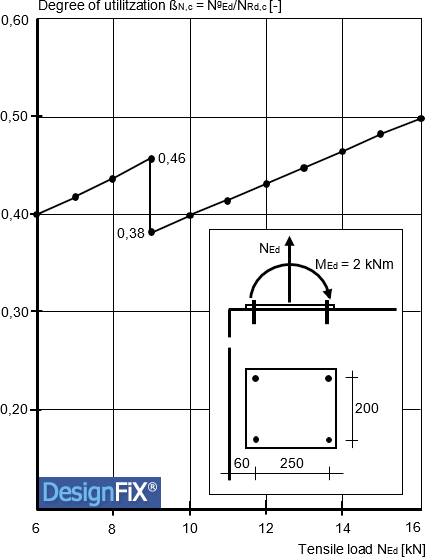
Figure 1:
Degree of utilization of a group with four chemical anchors M12 close to an edge for ‘Concrete cone failure’ as a function of the acting tension load (Mallée, R.: Anmerkungen zur Bemessung von Dübeln nach europäischen Regelungen (Comments on the design of anchors according to European regulations). Ernst + Sohn, Berlin, Beton- und Stahlbetonbau, 2014, pp. 699-712 (in German))
The degree of utilization increases up to a tensile load NEd ≈ 9 kN and falls abruptly by approximately 17% when this load is exceeded. This step contradicts the expectations of the users, who naturally assume that a higher load also leads to a greater utilization of the fastening. This discontinuity has the following reason:
Up to a tensile load NEd ≈ 9 kN, only the two anchors close to the edge are subjected to tension, while the two anchors remote from the edge are located in the compression zone under the anchor plate and are therefore not subjected tension and have in accordance with ETAG 001, Annex C, Section 4.2.1c not to be considered (European Organisation for Technical Approvals (EOTA): Guideline for European Technical Approval of Metal Anchors for Use in Concrete. Annex C: Design Methods for Anchorages. Brussels 1997, amendments 2001, 2006 und 2010). If the tensile load exceeds the value NEd ≈ 9 kN, then the size of the compression zone under the anchor plate decreases accordingly, with the result that the two anchors remote from the edge are no longer located in the compression zone and are therefore also tensioned. The different loads of the anchors close to and remote from the edge are taken into account by means of the eccentricity factor ψec,N according to Riemann (Riemann, H .: The extended “κ-method” for fasteners, dimensioning using the example of head bolt anchorages. Betonwerk + Fertigteil-Technik, 1985, pp. 808-815).
If all the anchors are subjected to tension, then the edge influence is “smeared” on all four anchors of the group, that is, the two anchors remote from the edge positively influence the bearing behavior of the front anchors. If only the two front anchors are subjected to tension for loads NEd > 9 kN, then this positive influence is eliminated and the degree of utilization increases correspondingly.
These steps in the resistance also occur in the case of failure modes ‘Splitting’ and ‘Combined pull-out and concrete failure (chemical anchors)’, since the same geometric model is used as in the case of ‘Concrete cone failure’.
As described in Part 3 of these posts, one possible solution would be to modify the current design method so that the resistance of each individual anchor in the group is calculated and compared with the load acting on this anchor. The anchor with the highest degree of utilization would then be decisive for the failure of the whole group. However, a corresponding approach for the consideration of load eccentricity has so far been lacking. The eccentricity factor ψec,N used in the current design method is valid for the group and not for the individual anchors of a group (Riemann, H .: Das “erweiterte κ-Verfahren” für Befestigungsmittel, Bemessung an Beispielen von Kopfbolzenverankerungen. (The “expanded κ-method” for fastenings, design examples for headed anchors). Betonwerk + Fertigteil-Technik, Vol. 12, pp. 808-815).
Until then, the steps in the load bearing capacity of anchor groups close to an edge cannot be avoided.


Contents of the DesignFiX - Trial version
This demo version is designed primarily for anchor manufacturers and distributors, and includes the product range of a virtual company called Your Company. The implemented products include chemical and mechanical anchors. More information about installation and system requirements.