
3D Anchor Design
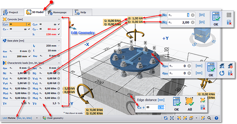
The 3D-Model shows your application including concrete component (base material), attachment, anchor layout, profile and loads. Based on this information a design is carried out for the selected anchor in real time at any change of the entered data and the result is displayed in the status bar.
Input of geometric data
With a click on the dimension line or on the corresponding value you open the input editor. The editor shows either a single input field – e. g. for the edge distance – or two related fields – e. g. for the attachment (length and height of the plate). Once the new input values have been confirmed with the OK button DesignFiX performs immediately a new design in the background. Some editors also offer the ability to accept the entered value directly for adjacent dimensions (e. g., accept the edge distance for all component edges or accept the axial spacing for all spacing of this axis). In the event that you decide not to change the data (e. g., editor was opened accidentally) you can directly open the editor for the next input value without using the button Cancel.
Input of loads
With a click on a load value in the 3D-Model you open the input editor for the loads. Depending on the type of loads (design loads or characteristic loads) the anchor offers a single input field or two fields for permanent loads (G) and variable loads (Q). You can alter the partial safety factors in the tabular input window.
Optionally, you can specify on the tab VIEW how the values should be displayed in the 3D view (e. g. with legend). In addition, you can determine whether the value when opening editor shall be marked automatically for direct overwriting. This feature allows you a quick and comfortable data entry.
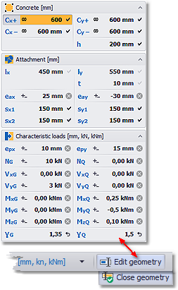
Tabular input
The function ‘Edit geometry’ and ‘Close geometry’ offers an alternative input option. In the tabular input, you can enter all loads and all geometric dimensions quickly and comfortably. Once you alter any of these values, the 3D-Model and the design are immediately updated in real time in the background. You don’t have to confirm any of the values. By pressing the Return key or the Tab key on your keyboard the next input field is activated directly.
Hover effect:
A direct link exists between the input fields of the 3D-drawing and the input window. If the cursor is positioned in an input field of the 3D-drawing then the corresponding field in the input window is marked (hover effect) and vice versa. This makes it easier to navigate. Additional options for dimensioning and displaying additional information (e. g. legends) can be found on the tab VIEW.
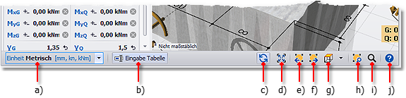
- a) Switching the units in metric [mm, kN, kNm] or imperial [inch, lb, ft-lb] – compare tab START
- b) Shows/hides the window for tabular load and geometry input
- c) Standard view – the 3D-Model will be repainted and fitted into the window
- d) Fitting – the 3D-Model fits into the current window
- e) Rotate – the 3D-Model is rotated by 45° clockwise
- f) Rotate – the 3D-Model is rotated by 45° counter-clockwise
- g) Top view – more views are available as Options
- h) Detail zoom – a specific area can be zoomed with the mouse
- i) Zoom – the 3D-Model is enlarged or reduced
- j) Displays the help text for 3D-Model


Contents of the DesignFiX - Trial version
This demo version is designed primarily for anchor manufacturers and distributors, and includes the product range of a virtual company called Your Company. The implemented products include chemical and mechanical anchors. More information about installation and system requirements.