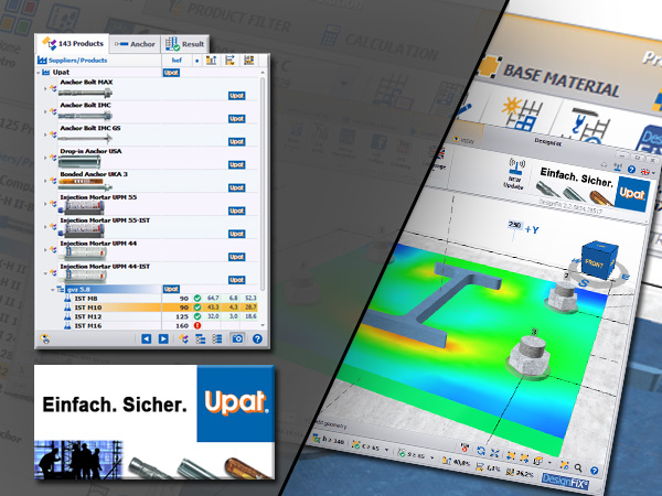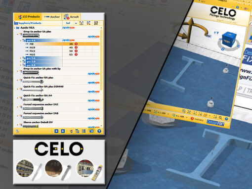
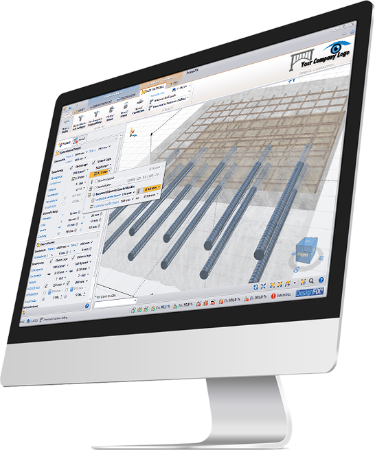
Now available: Design of post-installed rebar connections in reinforced concrete.
Powerful injection systems are ideal for post-installed rebar connections. The injection mortar is injected into the thoroughly cleaned bore hole and then the reinforcing bar is inserted. After curing of the mortar, the new component can be concreted. Rebar connections are used both in new construction as well as retrofitting or changes in use of existing structures.
New DesignFiX software module:
Design of post-installed rebar connections in reinforced concrete.
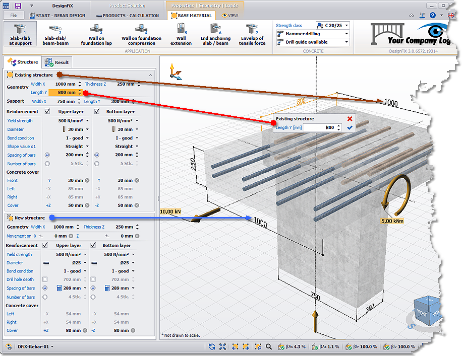
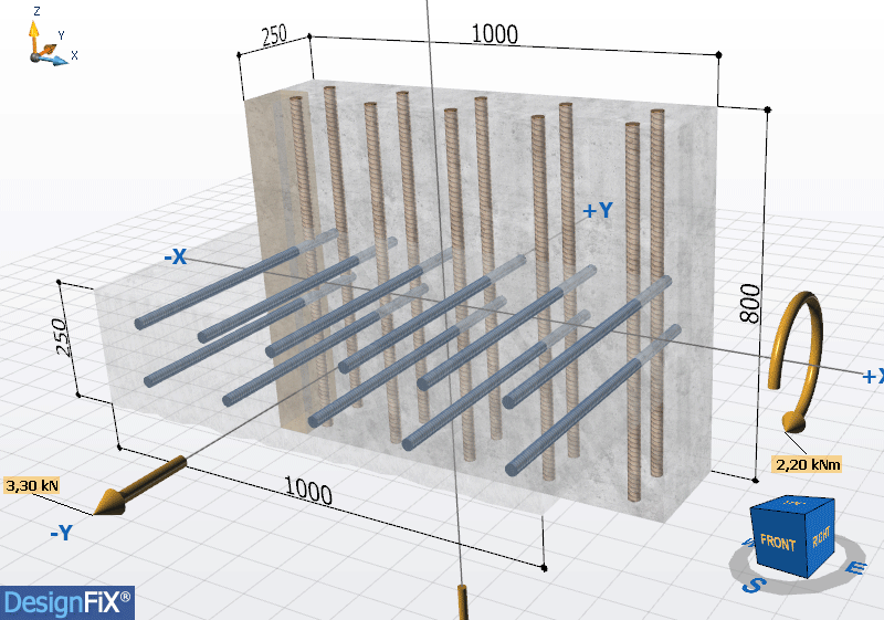
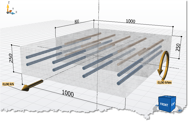
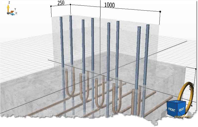
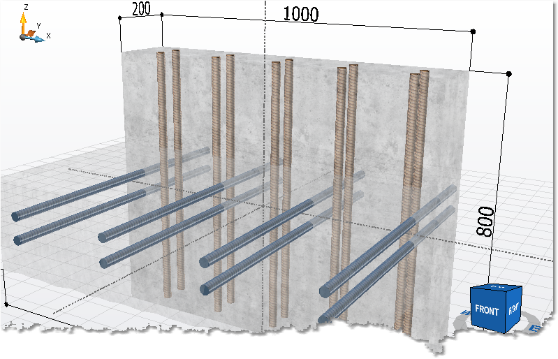
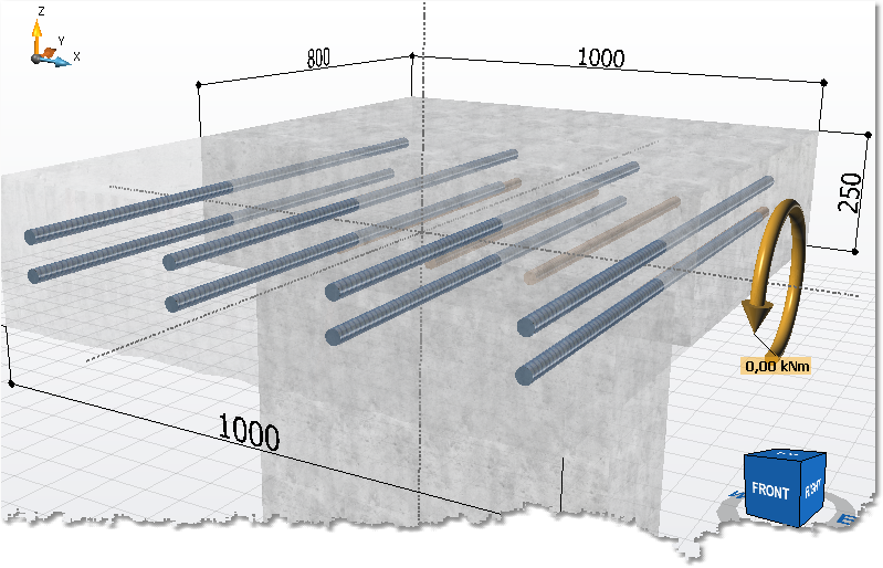
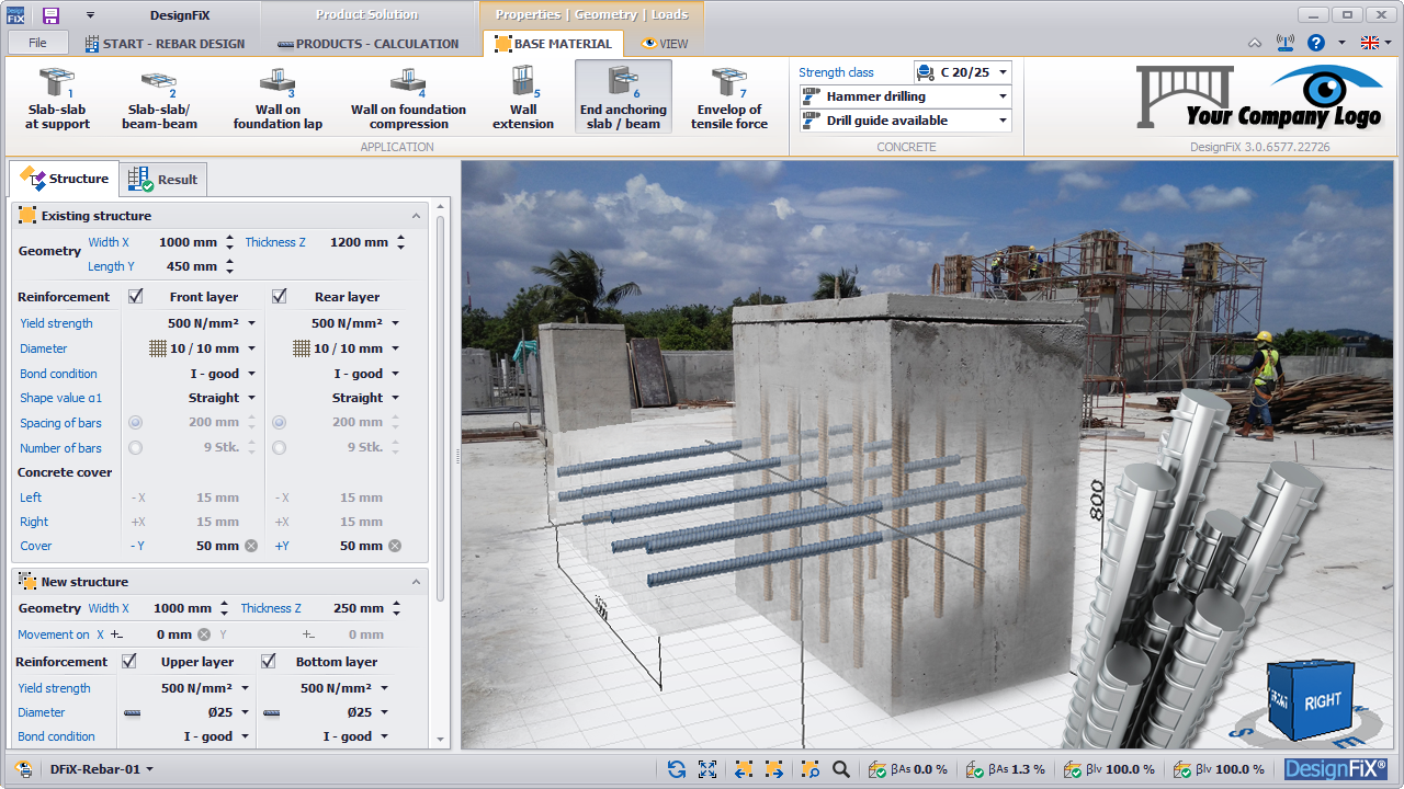
The Structure tab presents two main sections of the 3D model:
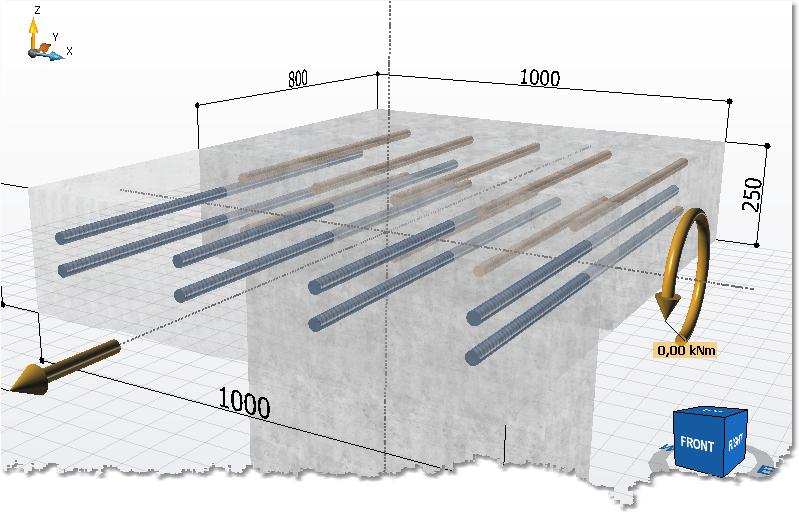
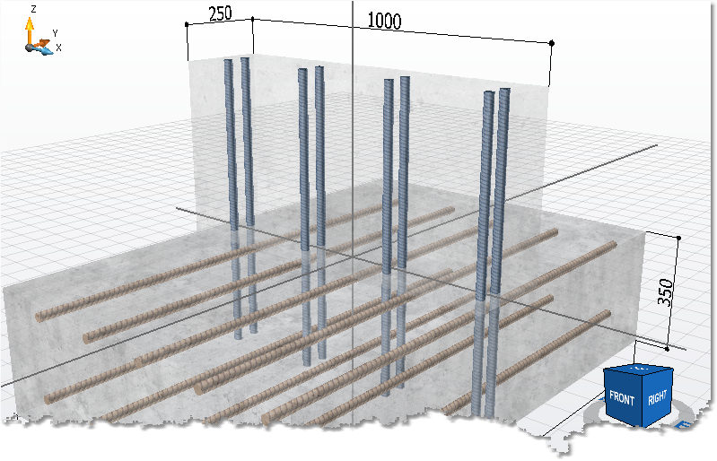
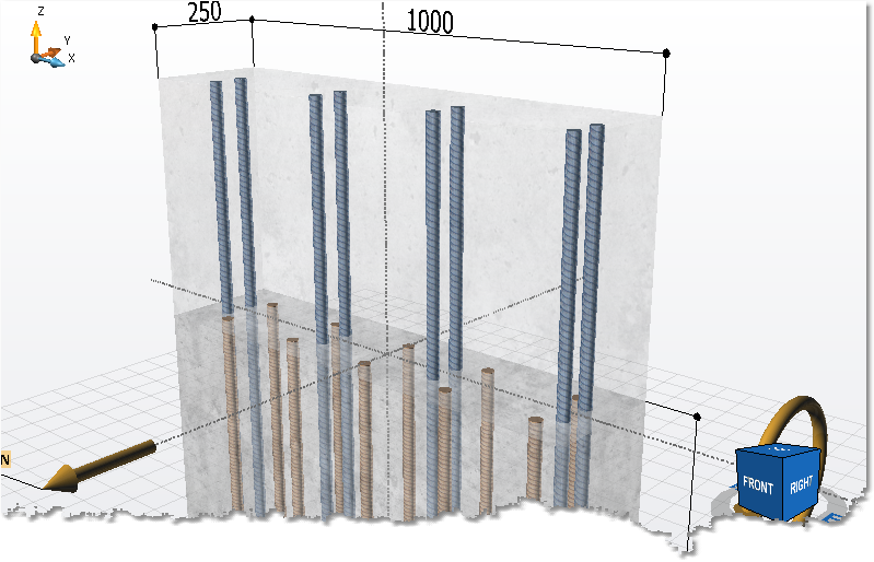
The existing component and the new component, each with all necessary geometric properties.
Hover effect:
A direct link exists between the input fields of the 3D-drawing and the input window. If the cursor is positioned in an input field of the 3D-drawing then the corresponding field in the input window is marked (hover effect) and vice versa. This makes navigation easier.
1) Slab to slab on support / beam to beam on support:
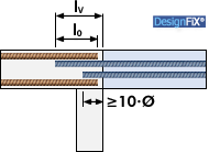
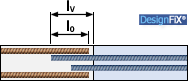
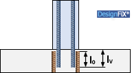
Connection of a plate or a beam to an existing supported component by overlapping the reinforcement (reinforcement lap).
2) Slab to slab / beam to beam:
Connection of a plate or a beam to an existing component by overlapping the reinforcement (reinforcement lap).
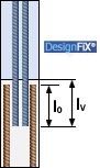
3) Wall to foundation / column to foundation (lap):
Connection of a wall or column to an existing foundation by overlapping the reinforcement (reinforcement lap).
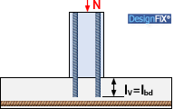
4) Wall to foundation / column to foundation
Connection of a wall or column under compression to an existing foundation (only compression force N permitted).
5) Wall extension / beam extension:
Connection of a wall or a column to an existing component by overlapping the reinforcement (reinforcement lap).
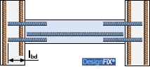
6) End anchoring of wall or beam:
End anchoring of a simply supported slab or a beam (only shear force V permitted).
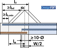
7) Envelop of tensile force:
Anchoring of reinforcement to cover the envelop of the tensile force in a component (plate or beam) subjected to bending.
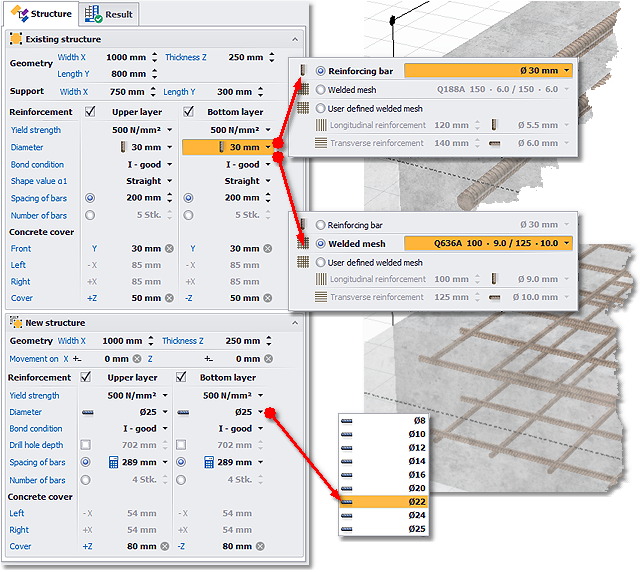
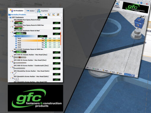
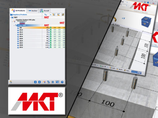
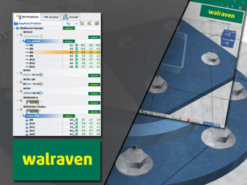
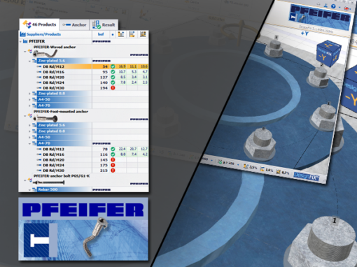
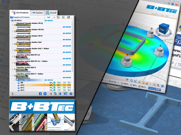
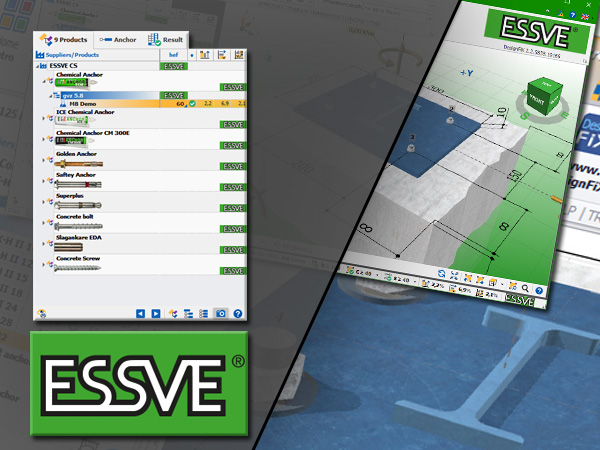
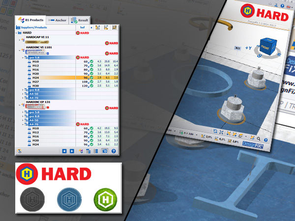
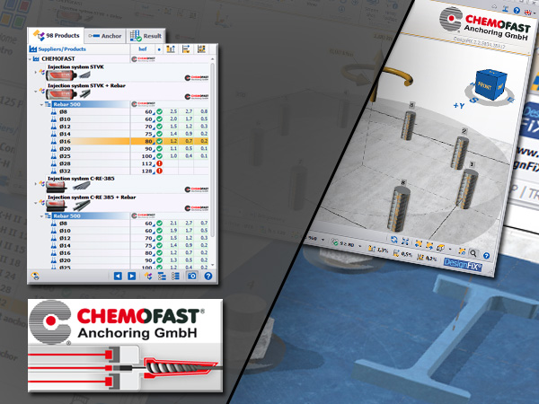
In the tabular input, you can enter all geometric dimensions quickly and comfortably. Once you alter any of these values, the 3D-Model and the design are immediately updated in real time in the background. You do not have to confirm any of the values. By pressing the Return key or the Tab key on your keyboard the next input field is activated directly.
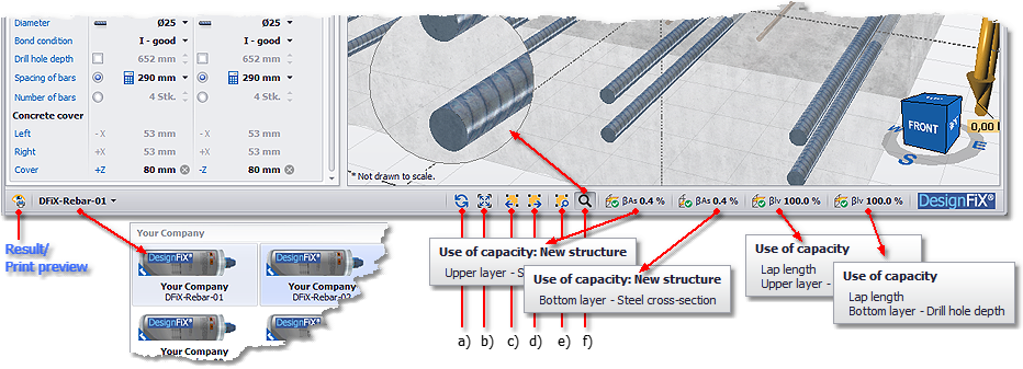
The status bar in DesignFiX provides you with important information about the result of the calculation and always refers to the currently selected product. Depending on the content of the window, the status bar can be multiline.
The following information areas are included in DesignFiX:
- Standard view – the 3D-Model will be refreshed and fitted into the window.
- Fitting – the 3D-Model fits into the current window.
- Rotate – the 3D-Model is rotated by 45° clockwise
- Rotate – the 3D-Model is rotated by 45° counter-clockwise.
- Detail Zoom – defines a rectangular zoom area.
- Magnifier – defines a circular area as an interactive magnifying glass.
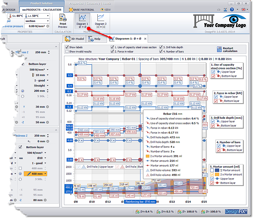
Multi design #1
The function Diagram 1 (Ø = Ø) performs a multiple design of the currently selected product. All available diameters are investigated separately (equal diameters in both reinforcement layers) and the result is displayed in five diagrams. The X-axis of the diagram contains the diameters and the Y-axes the respective results like:
- Use of capacity
- Force in rebar
- Drill hole depth
- Number of bars
- Mortar amount
The individual layers (upper/bottom or front/rear) can be switched on or off in the legend.
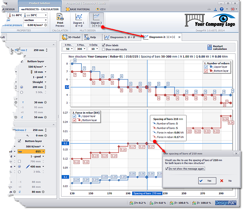
Multi design #2
The function Diagram 2 (s = s) also performs a multiple design, maintaining the diameter of the selected rebars and altering the spacings in the given increment X-delta from X-Min to X-Max.